8.4 Verilog ACC 子程序
功能特性
ACC 子程序主要完成的功能有:
- 从内部数据结构中读取特定对象的相关信息
- 把特定对象的相关信息写入内部数据结构中
ACC 子程序可操作的对象类型有:
- 模块实例、模块端口、模块的端到端的路径以及模块之间的路径
- 顶层模块
- 原语实例和原语端口
- wire、reg、parameter、integer、time、real 等变量类型
- 时序检查
- 命名事件
ACC 子程序的主要特征有:
- 均以 acc_ 为前缀
- 开头必须调用 acc_initialize() 以进行环境初始化
- 退出时必须调用 acc_close()
- 使用 ACC 库中的函数时必须包含头文件 acc_user.h
- 使用句柄的概念访问对象。句柄是预定义的指向设计中特定对象的数据类型。获取到句柄就能获取到对象的全部信息。这与 C 语言中文件的句柄概念类似。句柄用关键字 handle 声明。
ACC 子程序的主要类型有:
- 句柄子程序(handle):将句柄返回设计中的对象,总是以 acc_handle_ 为前缀。
- 后继子程序(next):将句柄返回给设计中特定对象集合中的下一个对象,总是以 acc_next_ 为前缀,而且以引用的对象作为参数。
- 值变链接子程序(VCL, Value Change Link):可以从监视对象值变化的对象列表中添加和删除对象,总是以 acc_vcl_ 为前缀,没有返回值。
- 取值子程序(fetch):能够提取层次路径等属性信息,总是以 acc_fetch_ 为前缀。
- 杂项子程序(miscellaneous):用于执行与存取子程序相关的一些杂项操作,例如 acc_initialize() 与 acc_close() 都属于杂项子程序。
- 修改子程序(modify):可以修改内部数据结构。
完整的 ACC 子程序及其简单用法说明参考下一节《8.5 ACC 子程序列表》。
ACC 子程序举例
下面仅对一些 ACC 子程序进行使用举例,主要说明使用 ACC 子程序设计 Verilog 系统任务的基本流程。
设计需求
本次设计一个计数器监测的系统任务。
一方面该系统任务监测 Verilog 中计数器的值,一方面在检测到 Verilog 中计数时钟后也进行软件计数,并将软、硬件计数值作对比,以检查硬件逻辑的正确性。同时在计数器计数到特定值时,将一些信号变量值输出。
该设计思想也是 PLI 接口经常使用的场景。软件完成一种逻辑功能,称之为 CModel。然后硬件也使用 Verilog 完成相同的逻辑功能。通过 PLI 接口程序,软硬件程序可以同时执行并进行结果对比,以验证硬件逻辑设计的正确性。
设计分析
PLI 接口部分使用值变链接子程序对时钟进行监视。时钟上升沿一旦来临,就调用软件函数,进行软件计数,并对比软硬件计数值。
软件设计
软件设计代码如下,细节在注释中说明,保存到文件 monitor_gyc.c 中。
实例
handle hand_rstn , hand_clk , hand_cnt , hand_cout ;
int cnt_soft = 0 ; //软件计数器的值
int cout_soft = 0 ; //软件计数器的溢出位
//软件计数、对比函数
void act_monitor ( ) {
p_acc_value value ; //声明 ACC 中定义的结构体变量
//读取 Verilog 中信号变量的值,字符串类型
char *rstn_rtl_str = acc_fetch_value (hand_rstn , "%d" , value ) ;
char *clk_rtl_str = acc_fetch_value (hand_clk , "%d" , value ) ;
char *cnt_rtl_str = acc_fetch_value (hand_cnt , "%d" , value ) ;
char *cout_rtl_str = acc_fetch_value (hand_cout , "%d" , value ) ;
//字符串转整型
int rstn_rtl = atoi (rstn_rtl_str ) ;
int clk_rtl = atoi (clk_rtl_str ) ;
int cnt_rtl = atoi (cnt_rtl_str ) ;
int cout_rtl = atoi (cout_rtl_str ) ;
//软件计数器
//复位
if ( !rstn_rtl ) {
cnt_soft = 0 ;
cout_soft = 0 ;
io_printf ( "---iii--- Reset state! \n" ) ;
}
//正常工作
else if (rstn_rtl && clk_rtl ) {
if (cnt_soft == 9 ) {
cnt_soft = 0 ; //计数10个
}
else {
cnt_soft = cnt_soft + 1 ; //计数
}
}
cout_soft = cnt_soft == 9 ? 1 : 0 ; //进位
//在时钟为低的时间对比软硬件计数,此时为相对安全的时刻
if ( !clk_rtl && rstn_rtl ) {
if ( (cnt_soft != cnt_rtl ) || (cout_soft != cout_rtl ) ) {
io_printf ( "--Err--- rtl cnt: %d, and soft cnt: %d\n" , cnt_rtl , cnt_soft ) ;
io_printf ( "--Err--- rtl cout: %d, and soft cout: %d\n" , cout_rtl , cout_soft ) ;
}
//软硬件计数对比没有错误,则输出一次计数完结时信号的状态值
else if (cnt_soft == 9 ) {
io_printf ( "--Monitor--- rtl and soft cnt: %d\n" , cnt_soft ) ;
io_printf ( "--Monitor--- rtl and soft cout: %d\n" , cout_soft ) ;
}
}
}
//PLI 接口,监测时钟变化
void my_monitor ( ) {
acc_initialize ( ) ; //必须进行初始化
//获取系统任务 my_monitor 第一个参数的 handle 变量
hand_rstn = acc_handle_tfarg ( 1 ) ;
hand_clk = acc_handle_tfarg ( 2 ) ;
hand_cnt = acc_handle_tfarg ( 3 ) ;
hand_cout = acc_handle_tfarg ( 4 ) ;
//"#define VCL_VERILOG_LOGIC 2" in acc_user.h
//Indicates the VCL callback mechanism shall report
//hand_clk 一旦变化,则调用 act_monitor 函数
acc_vcl_add (hand_clk , act_monitor , null , vcl_verilog_logic ) ;
acc_close ( ) ; //关闭任务
}
硬件设计
10 进制计数器的 Verilog 描述如下,保存到文件 counter10.v 中。
实例
input rstn ,
input clk ,
output [ 3 : 0 ] cnt ,
output cout ) ;
reg [ 3 : 0 ] cnt_temp ;
always @ ( posedge clk or negedge rstn ) begin
if ( ! rstn ) begin
cnt_temp <= 4'b0 ;
end
else if (cnt_temp == 4'd9 ) begin
cnt_temp <= 4'b000 ;
end
else begin
cnt_temp <= cnt_temp + 1'b1 ;
end
end
assign cout = (cnt_temp == 4'd9 ) ;
assign cnt = cnt_temp ;
endmodule
testbench
testbench 描述如下,保存到文件 test.v 中。
实例
module test ;
reg rstn , clk ;
wire [ 3 : 0 ] cnt ;
wire cout ;
initial begin
rstn = 0 ;
clk = 0 ;
# 19.8 ;
rstn = 1 ;
end
always # 5 clk = ~clk ;
counter10 u_cnt (
.rstn (rstn ) ,
.clk (clk ) ,
.cnt (cnt ) ,
.cout (cout ) ) ;
initial begin
$my_monitor (test.rstn , test.clk , test.cnt , test.cout ) ;
end
initial begin
forever begin
# 100 ;
if ( $time >= 300 ) $finish ;
end
end
endmodule
编译仿真
Linux 下用如下命令对 monitor_gyc.c 进行编译,输出 monitor_gyc.o 文件,注意相对路径。
gcc -I ${VCS_HOME}/include -c ../tb/monitor_gyc.c
使用 VCS 编译,需要创建 VCS 可识别的链接文件,文件命名为 pli_gyc.tab, 内容如下。
$my_monitor 是 Verilog 调用的系统任务名字;
call=my_monitor 表示调用软件 C 程序中的函数 my_monitor();
acc=rw:* 表示设置系统任务的属性,rw 表示可以对内部数据进行读写,冒号后面可以声明该系统任务作用的模块或信号区域,":*" 表示可以作用到所有模块。
$my_monitor call=my_monitor acc=rw:*
VCS 编译时增加如下参数行。
-P ../tb/pli_gyc.tab
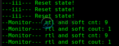
仿真结果 log 如下。
由 log 可知,软硬件计数对比正确,计数器完成一次周期计数的状态也正常。

本章节源码下载
Download
