
使用SPI位碰撞的Arduino上的多个模数转换器

我使用Nano Arduino(ATMega 328)与基于此代码的两个12位MCP3208 ADC芯片通信。我有另一个设备(LED驱动器TLC5940)连接到本页建议的管脚上,但由于我使用的是位碰撞,所以我使用的管脚不重要。因此,我的配置与上述示例相同,只是:
    For ADC 1:
    CLK -> Arduino D6
    DOUT (MISO) -> Arduino D5
    DIN (MOSI) -> Arduino D12
    SS -> Arduino D7

    For ADC 2:
    CLK -> Arduino D6
    DOUT (MISO) -> Arduino D5
    DIN (MOSI) -> Arduino D12
    SS -> Arduino D8
所以,问题是我从ADC 1获取数据,而不是从ADC 2。我应该能够通过将选择引脚拉低来选择ADC 2,但我得到的是0。有16个光电二极管连接到4个TLC2274运算放大器。这里是Arduino代码:
//Scott Little, BrainGoggles, 2013, GNU GPL v3
#include <SoftwareSerial.h>
#include "Tlc5940.h"
SoftwareSerial bluetooth(4,2);  //TX 4, RX 2

#define SELPIN 7 //Selection Pin for 1st ADC
#define SELPIN2 8 //Selection Pin for 2nd ADC
#define DATAOUT 12//MOSI
#define DATAIN  5//MISO
#define SPICLOCK  6//Clock
int readvalue;
byte readvaluearray[32];
int intensity = 0;

void setup()
{
  /* Call Tlc.init() to setup the tlc.
     You can optionally pass an initial PWM value (0 - 4095) for all channels.*/
  Tlc.init();  //interferes with other SPI
  Tlc.clear();  //set pin modes

  pinMode(SELPIN, OUTPUT); //adc 1 selection pin
  pinMode(SELPIN2, OUTPUT); //adc 2 selection pin
  pinMode(DATAOUT, OUTPUT);
  pinMode(DATAIN, INPUT);
  pinMode(SPICLOCK, OUTPUT);
  //disable devices to start with
  digitalWrite(SELPIN,HIGH);
  digitalWrite(SELPIN2,HIGH);
  digitalWrite(DATAOUT,LOW);
  digitalWrite(SPICLOCK,LOW);
  bluetooth.begin(9600);
  Serial.begin(9600);

}

void loop()
{
  if (bluetooth.available()) // Wait until a character is received
  {
    char val = (char)bluetooth.read();
    Serial.println(val);

    switch(val) // Perform an action depending on the command
    {
      case 't'://increase intensity when an 'e' is received
    intensity = plus(intensity);
      break;

      case 'y'://decrease intensity when an 'r' is received
    intensity = minus(intensity);
      break;

      case 'q'://turn the light on when a 'q' is received
    on();
      break;

      case 'w'://turn the light off when a 'w' is received
    off();
      break;
    }
  }

  for (int i=0; i<8; i++){        //read from ADC 1
    readvalue = read_adc(i+1);
    readvaluearray[2*i] = highByte(readvalue);
    readvaluearray[2*i+1] = lowByte(readvalue);
  }

  for (int i=8; i<16; i++){        //read from ADC 2
    readvalue = read_adc2(i-7);
    readvaluearray[2*i] = highByte(readvalue);
    readvaluearray[2*i+1] = lowByte(readvalue);
  }

  bluetooth.write(readvaluearray,32);
  Serial.println("new");
  for (int i=0;i<16;i++){
    Serial.println(word(readvaluearray[2*i],readvaluearray[2*i+1]));
  }

  delay(2000);
}


int read_adc(int channel){
  int adcvalue = 0;
  byte commandbits = B11000000; //command bits - start, mode, chn (3), dont care (3)

  //allow channel selection
  commandbits|=((channel-1)<<3);

  digitalWrite(SELPIN,LOW); //Select adc

  // setup bits to be written
  for (int i=7; i>=3; i--){
    digitalWrite(DATAOUT,commandbits&1<<i);
    //cycle clock
    digitalWrite(SPICLOCK,HIGH);
    digitalWrite(SPICLOCK,LOW);
  }

  digitalWrite(SPICLOCK,HIGH);    //ignores 2 null bits
  digitalWrite(SPICLOCK,LOW);
  digitalWrite(SPICLOCK,HIGH);
  digitalWrite(SPICLOCK,LOW);

  //read bits from adc
  for (int i=11; i>=0; i--){
    adcvalue+=digitalRead(DATAIN)<<i;
    //cycle clock
    digitalWrite(SPICLOCK,HIGH);
    digitalWrite(SPICLOCK,LOW);
  }
  digitalWrite(SELPIN, HIGH); //turn off device

  return adcvalue;
}

int read_adc2(int channel){
  int adcvalue = 0;
  byte commandbits = B11000000; //command bits - start, mode, chn (3), dont care (3)

  //allow channel selection
  commandbits|=((channel-1)<<3);

  digitalWrite(SELPIN2,LOW); //Select adc

  // setup bits to be written
  for (int i=7; i>=3; i--){
    digitalWrite(DATAOUT,commandbits&1<<i);
    //cycle clock
    digitalWrite(SPICLOCK,HIGH);
    digitalWrite(SPICLOCK,LOW);
  }

  digitalWrite(SPICLOCK,HIGH);    //ignores 2 null bits
  digitalWrite(SPICLOCK,LOW);
  digitalWrite(SPICLOCK,HIGH);
  digitalWrite(SPICLOCK,LOW);

  //read bits from adc
  for (int i=11; i>=0; i--){
    adcvalue+=digitalRead(DATAIN)<<i;
    //cycle clock
    digitalWrite(SPICLOCK,HIGH);
    digitalWrite(SPICLOCK,LOW);
  }
  digitalWrite(SELPIN2, HIGH); //turn off device

  return adcvalue;
}

void on(void)
{
  Tlc.set(1, 4095);  //set pin 5 to max brightness
  Tlc.update();  //execute set
  //bluetooth.println("on");
  //Serial.println("on");
}

void off(void)
{
  Tlc.set(1, 0);  //set pin 5 to min brightness
  Tlc.update();  //execute set
  //bluetooth.println("off");
  //Serial.println("off");
}

int plus(int value)
{
  value = value + 64;
  if (value > 4095){value = 4095;}
  Tlc.set(1, value);  //set pin 5 to min brightness
  Tlc.update();  //execute set
  Serial.println(value);
  return value;
}

int minus(int value)
{
  value = value - 64;
  if (value < 0){value = 0;}
  Tlc.set(1, value);  //set pin 5 to min brightness
  Tlc.update();  //execute set
  Serial.println(value);
  return value;
}
下面是我得到的示例输出:
new
374
372
311
313
356
276
337
387
0
0
0
0
0
0
0
0
共有2个答案

它现在正在工作。我将ADC上对应于DOUT(ADC 12)的管脚物理更改为Arduino上对应于MISO(Arduino 12)的管脚,并将代码更改为:
#define DATAOUT 5  //MOSI
#define DATAIN  12 //MISO
它应该像我以前那样工作,因为我有点砰砰作响,但它现在似乎工作了,因为味噌是在“正确的”引脚。
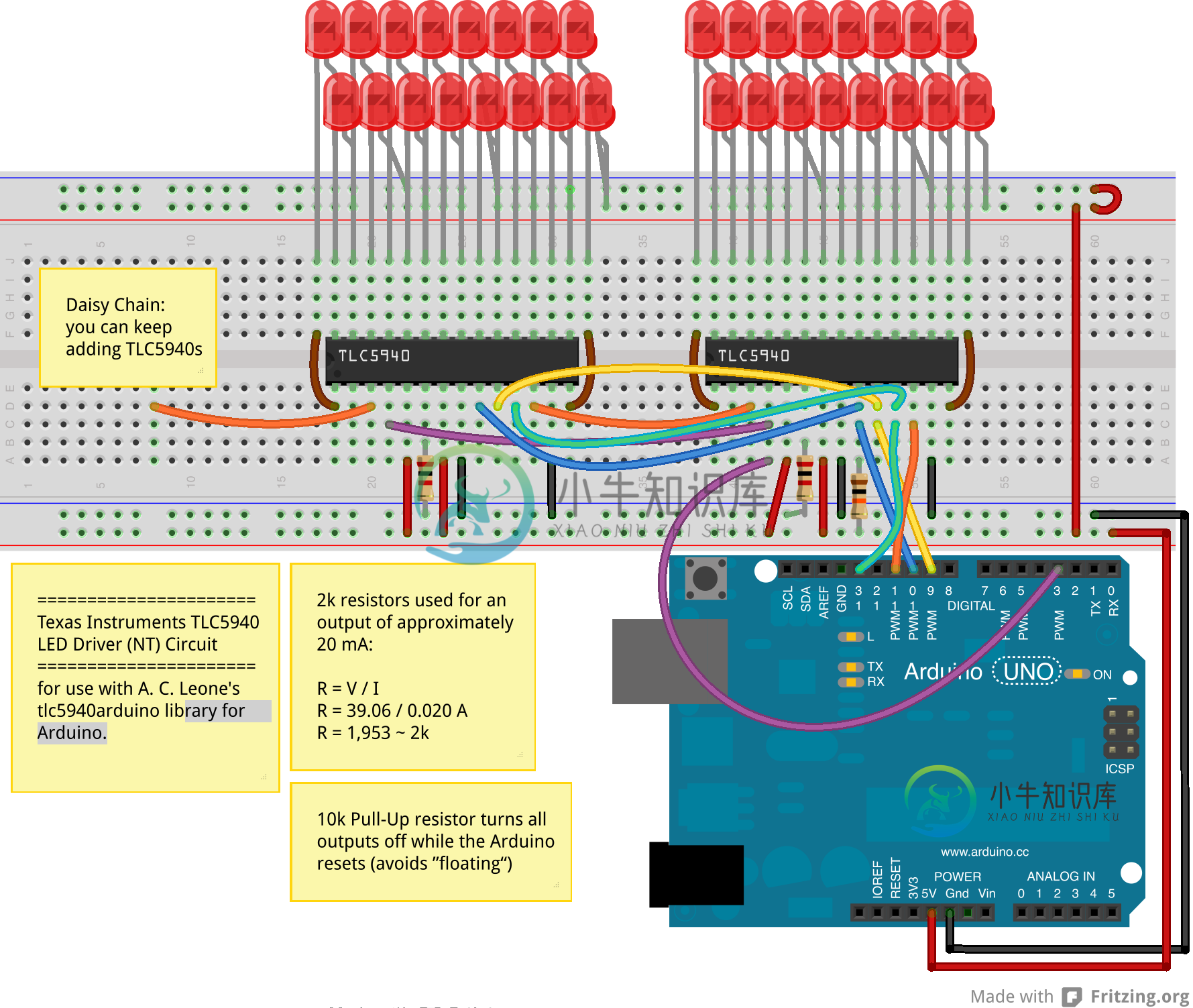
我设计了一个草图,用于在我的Arduino uno上使用TLC5940驱动10个(或更多)RGB LED。这可能也适用于nano。我在30个通道上驱动10个公共阳极rgb LED,两个TLC5940菊花链连接在一起。只要您配置使用的TLC5940芯片数量,我们就可以实现更多。这适用于12位占空比控制(0-4095)。
>
在arduino IDE中,必须从以下位置导入Paul Stoffregen的TLC5940库:https://github.com/PaulStoffregen/Tlc5940.
编辑tlc_config.h文件,其中NUM_TLCs应等于2(默认为1):
"#定义NUM_TLCS2"
现在我们可以看一下素描来运行它
虽然这描述了单色LED,但我将映射我的rgb引脚0-2、3-5、6-8、9-11…等等。
代码:
#include "Tlc5940.h"

int rgbChannels = 30;//total channels used one the TLC5940's
int rgb[30]; ///should be the same as the number of channels
int rgbLights = 10;/// this is the number of rgb leds possible on 2 TLC5940's but you could always daisy chain more...
int colorArray[10];//this sets the number of colors to use (one per rgb led)

void setup() {
  // put your setup code here, to run once
  Tlc.init(0); // Initiates the TLC5940 and set all channels off
  Serial.begin(250000);
  Serial.println("Total Channels: " + String(rgbChannels) + "  Total
RGB Ligts: " + String(rgbLights));
  float divisor = 360 / (rgbChannels / 3); //degrees of color to
display divided by the number of rgb lights
  Serial.println("Divisor: " + String(divisor) );
  float Step = divisor;
  for (int i = 0; i < rgbLights; i++) {
    colorArray[i] = Step;
    Serial.println("colorArray[" + String(i) + "]: " + String(colorArray[i]));
    Step = Step + divisor;
  }
}

void ledColor(int channel, int red, int green, int blue)
{
  Tlc.set(channel, red);
  Tlc.set(channel + 1, green);
  Tlc.set(channel + 2, blue);
}

///convert hsi color to rgb
void hsi_to_rgb(int startChannel, float H, float S, float I) {
  int r, g, b;
  if (H > 360) {
    H = H - 360;
  }
  // Serial.println("H: "+String(H));
  H = fmod(H, 360); // cycle H around to 0-360 degrees
  H = 3.14159 * H / (float)180; // Convert to radians.
  S = S > 0 ? (S < 1 ? S : 1) : 0; // clamp S and I to interval [0,1]
  I = I > 0 ? (I < 1 ? I : 1) : 0;
  if (H < 2.09439) {
    r = 4095 * I / 3 * (1 + S * cos(H) / cos(1.047196667 - H));
    g = 4095 * I / 3 * (1 + S * (1 - cos(H) / cos(1.047196667 - H)));
    b = 4095 * I / 3 * (1 - S);
  } else if (H < 4.188787) {
    H = H - 2.09439;
    g = 4095 * I / 3 * (1 + S * cos(H) / cos(1.047196667 - H));
    b = 4095 * I / 3 * (1 + S * (1 - cos(H) / cos(1.047196667 - H)));
    r = 4095 * I / 3 * (1 - S);
  } else {
    H = H - 4.188787;
    b = 4095 * I / 3 * (1 + S * cos(H) / cos(1.047196667 - H));
    r = 4095 * I / 3 * (1 + S * (1 - cos(H) / cos(1.047196667 - H)));
    g = 4095 * I / 3 * (1 - S);
  }
  rgb[0 + startChannel] = r;
  rgb[1 + startChannel] = g;
  rgb[2 + startChannel] = b;

}


void rainbowShift() {
  float brightness = .4;
  float saturation = 1;
  for (int n = 0; n <= 360; n++) {
    for (int i = 0, j = 0; i < rgbLights; i++) {
      hsi_to_rgb(j, colorArray[i] + n, saturation, brightness);
      //Serial.println("rgb"+String(i)+":"+String(rgb[j])+","+String(rgb[j+1])+","+String(rgb[j+2]));
      ledColor(j, rgb[j], rgb[j + 1], rgb[j + 2]);
      j = j + 3;
    }
    Tlc.update();
    Tlc.clear();
    delayMicroseconds(500);
  }
}


void loop() {
  // put your main code here, to run repeatedly:
rainbowShift();////perform the function a few times

}
当所有这些都完成后,你应该在你的RGB LED上看到一道变换的彩虹
查看此视频:
<iframe width="560" height="315" src="https://www.youtube.com/embed/CWdL9i8U8U0" frameborder="0" allowfullscreen></iframe>-
我已经寻找并找到了单个碰撞的答案,但我正在寻找一种检测多种类型的碰撞的方法。我正在制作一个游戏,其中有3个我想要的碰撞。用户飞机与敌方子弹相撞,用户子弹与敌机相撞(我已经工作过),敌方子弹与用户子弹相撞。我已经设置并更正了所有类别BitMask和contactTestBitMask。这是我的委托方法。
-
我使用JavaSlick StateBaeedGame,并希望旋转我的矩形我的碰撞,我知道这是可以做的视觉目的使用图形或Graphics2D对象,但不修改矩形本身,最初列出的变量和图形方法中调用的矩形不旋转,使事情更清楚这里是一些代码: 当我加载GUI时,矩形rectTwo将显示为旋转,但它实际上并没有旋转,如果我测试碰撞,矩形仍然为0度。 那么,如何让矩形变量改变其角度呢?
-
获取碰撞器组件 Cocos Creator 3D 目前支持两种语言进行开发,分别为JavaScript和TypeScript。 注:TypeScript具有良好的语法分析和类型提示,推荐使用。 以获取BoxCollider为例,在JavaScript中获取Collider组件: this.getComponent('BoxCollider') this.getComponent(BoxCollid
-
我下面的碰撞方法有问题。问题是当游戏中有两个敌人时。它与循环中的一个敌人相交,然后返回true进行碰撞。但是如果在这个数组列表中有第二个敌人,它将不会与第二个物体碰撞,因此导致它返回false,玩家继续行走。有什么办法可以让他在接触任何敌人时停下来,而不是因为他没有接触到所有的敌人而继续下去吗?谢谢,这是密码。
-
我目前正在尝试为2D游戏编写冲突检测方法,但我被卡住了。 相交()方法由经过敌人的玩家以及玩家和敌人的坐标调用。图像掩码对象具有一个 2 维布尔数组,该数组对应于子画面的掩码。面具缩放 4 倍,因为精灵在游戏中是 16x16 的,并且放大到 64x64。 这不太管用;有时它会按预期工作,但有时当实体不接触时,它会报告冲突,或者当实体相互重叠时,它不会报告冲突。如何修复此问题以使碰撞检测有效?
-
基本问题:当玩家在由多个对撞机组成的平面上移动时,Unity的物理引擎会产生奇怪的碰撞。重影碰撞发生在碰撞器之间的关节处,并表现为两种行为: 根据Bennett Foddy的演讲,这似乎是物理引擎的一个普遍问题: https://www.youtube.com/watch?v=NwPIoVW65pE 游戏细节:在我的例子中,玩家正在通过程序生成的虫洞移动,虫洞由使用网格对撞机分割的对象组成。虫洞在