
MATLAB中极坐标图像到笛卡尔图像的转换

我无法将[R,theta]格式的图像转换为[x,y]
我正在尝试使用interp2。
[nZ,nX] = size(im);
theta = ((0:(nX-1)))*0.0071; %0.0071 is known angular separation of columns
rr = (0:(nZ-1))*0.0039; %0.0039 is resolution of rows
然后我会:
%% Create grids and convert polar coordinates to rectangular
[THETA,RR] = meshgrid(theta,rr);
[XX,YY] = pol2cart(THETA,RR);
最后:
im_out=interp2(theta,rr,im,XX,YY,'linear');
im_out(isnan(im_out)) = 0;
但图像不正确!
以下是输入图像(图1)(带R,θ几何):
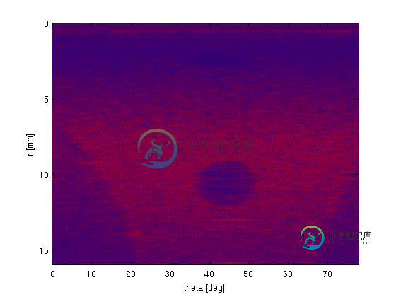
我想在笛卡尔网格上重建它(使用interp2),所以它看起来像这样(图2):
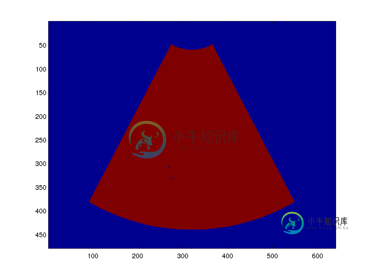
极坐标图像(图1)中的所有数据应映射到笛卡尔图像的红色部分(图2)。
共有1个答案

我设法做到了以下几点:
我在im矩阵的顶部添加了零,以正确定义曲率半径(在我的例子中为1018个像素,即ROC)和极坐标原点:
im = IML';   % scan_lines (rotated for now)
sector=75;   % [degrees]
im_depth=16; % [cm] (depth + ROC)

ROC=3.98;
im_depth=16+ROC;

col_size=size(im,2);
zeros_row = zeros(1018, col_size);
im=[zeros_row; im];
scan_lines = im;

[nY, nX] = size(im);

min_ang=(sector/nX)*pi/180;% [rad.]
theta = -nX/2*min_ang:min_ang:nX/2*min_ang; % total angle/num. lines [radians]
theta = theta(2:end);

steering_angles=theta; % angles [radians]

num_samples=im_depth/nY;
rr = (0:(nY-1))*num_samples; % im. depth/num. samples
r = rr;

image_size = [26.15,16+ROC]; % [cm]

x_resolution = 480; % image resolution [pix]
y_resolution = 640;

% assign the inputs
x = image_size(2);
y = image_size(1);

disp_rr=max(rr)/(im_depth-ROC);

%plot input image
%subplot(1,2,1); imagesc(theta*(180/pi), rr/disp_rr, fliplr(IML')); title('polar geometry'); colormap(gray)
%xlabel('theta [deg]')
%ylabel('r [cm]'); hold on;

% number of scan lines
Nt = length(scan_lines(1, :));

% create regular Cartesian grid to remap to
pos_vec_y_new = (0:1/(y_resolution-1):1).*y - y/2;
pos_vec_y_new = pos_vec_y_new';
pos_vec_x_new = (0:1/(x_resolution-1):1).*x;
[pos_mat_x_new, pos_mat_y_new] = ndgrid(pos_vec_x_new, pos_vec_y_new);

% convert new points to polar coordinates
[th_cart, r_cart] = cart2pol(pos_mat_x_new, pos_mat_y_new);

% interpolate using linear interpolation
op = interp2(steering_angles,r, scan_lines, th_cart, r_cart, 'linear').';

% set any values outside of the interpolation range to be 0
% op(isnan(op)) = max(b_mode(:));
op(isnan(op)) = 0;

%plot output image
subplot(2,2,4);
imagesc(pos_vec_y_new, pos_vec_x_new-ROC, op'); title('Cartesian geometry'); colormap(gray);
xlabel('lat [cm]')
ylabel('ax [cm]');
caxis([7.2,max(max(op))])
-
我知道这个问题已经被回答了很多次,但是我不知道我做的是好是坏。 我得到了一个带有缺陷位置和图像ID的文件。图像大小为96*96。起源是(48,48) 由此计算R和T 然后,我为每个图像创建大小为96×96的空矩阵,对于图像1(例如),我在每个坐标(R,T)处赋值0 当我绘制矩阵时,我的结果很奇怪。。我错过了什么重要的事情吗?
-
我想知道是否有人帮助我理解如何将顶部图像转换为底部图像。以下链接中提供了这些图像。顶部图像采用笛卡尔坐标。底部图像是极坐标中的转换图像
-
我正在尝试将极坐标的图像转换为笛卡尔坐标。 将图像转换为极坐标的示例显式执行-想要一个光滑的矩阵方法 我原以为使用上述方法是小菜一碟,但事实并非如此!!如果有人发现我的代码有错误,请告诉我! 我发现非常奇怪的是,当我改变phi时,它会做出根本性的改变,而不是以我期望的方式! 干杯
-
我试图计算一种有效的方法,将笛卡尔坐标系中的图像转换为极坐标表示。我知道ImToPolar等一些功能正在实现这一点,它工作得很好,但对于大图像来说需要相当长的时间,尤其是当它们需要来回处理时。 这是我的输入图像: 然后我使用以0为中心的笛卡尔网格和函数生成一个极网格。最后,我使用绘制我的图像。 这是我得到的: 这正是我需要的图像,它与ImToPolar相同,或者更好。 既然MATLAB知道如何计算
-
我一直在使用Peter Kovesi的MatLab函数进行机器视觉(如果你不知道的话,这些函数非常出色) 我一直在使用极坐标变换将图像转换为极坐标。Peter Kovesi的函数名为“PolarTrans”,可在此处找到-http://www.peterkovesi.com/matlabfns/#syntheticimages 该函数将图像漂亮地转换为极坐标。然而,我也希望发生相反的情况。Pete
-
我试图对下面的第一幅图像进行极坐标变换,最后得到第二幅。然而,我的结果是第三张图片。我有一种感觉,这与我选择的“原产地”有关,但我不确定。