
DrawingBrush中的相对坐标

我对WPF中相对坐标的工作方式有些困惑,尤其是在使用DrawingBrush的场景中。
假设我想画一个正方形区域的背景,它的大小是灵活的。我想用一种特殊的“形状”来绘制背景,比如说在侧面画一种“T”,垂直笔划穿过区域的中间。使用相对坐标(区域的大小是灵活的),我得出了以下XAML:
<Window x:Class="MainWindow"
    xmlns="http://schemas.microsoft.com/winfx/2006/xaml/presentation"
    xmlns:x="http://schemas.microsoft.com/winfx/2006/xaml"
    Title="MainWindow" Height="722" Width="722" UseLayoutRounding="True">
<Window.Resources>

    <DrawingBrush x:Key="EdgeGrid">
        <DrawingBrush.Drawing>
            <GeometryDrawing>
                <GeometryDrawing.Geometry>
                    <!-- draw a single T laying on the side -->
                    <GeometryGroup>
                        <!-- top to bottom -->
                        <LineGeometry StartPoint="0.5,0.0" EndPoint="0.5,1"/>
                        <!-- left to right -->
                        <LineGeometry StartPoint="0.5,0.5" EndPoint="1,0.5"/>
                    </GeometryGroup>
                </GeometryDrawing.Geometry>
                <GeometryDrawing.Pen>
                    <Pen Thickness="0.01" Brush="Black" />
                </GeometryDrawing.Pen>
            </GeometryDrawing>
        </DrawingBrush.Drawing>
    </DrawingBrush>
</Window.Resources>
    <Grid Name="LayoutRoot">
    <Rectangle Width="400" Height="400" Stroke="Black" StrokeThickness="1" Fill="{StaticResource EdgeGrid}">
    </Rectangle>

</Grid>
但我得到的结果是这样的:
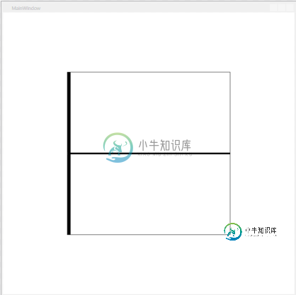
垂直笔划是否应该穿过中间(X坐标为0.5)?还有,如何在相对模式下将笔的厚度设置为1或2像素?有什么想法吗?
共有3个答案

让我们看看提议的解决方案是什么样子。假设我们想在一种网格中显示形状,并根据数据绘制各种形状(通过选择适当的日期模板)。为了简单起见,在本例中,我们只画一种形状(十字,如我的第一个问题所示):
<Window x:Class="MainWindow"
        xmlns="http://schemas.microsoft.com/winfx/2006/xaml/presentation"
        xmlns:x="http://schemas.microsoft.com/winfx/2006/xaml"
        Title="MainWindow" Height="722" Width="722" UseLayoutRounding="True">

    <ItemsControl ItemsSource="{Binding data}">
        <ItemsControl.ItemsPanel>
            <ItemsPanelTemplate>
                <UniformGrid Columns="10" Rows="10">
                </UniformGrid>
            </ItemsPanelTemplate>
        </ItemsControl.ItemsPanel>
        <ItemsControl.ItemTemplate>
            <DataTemplate>
                <Grid x:Name="Cell">
                   <Path StrokeThickness="2" Stroke="Blue" SnapsToDevicePixels="True">
                        <Path.Data>
                            <GeometryGroup>
                                <GeometryGroup.Transform>
                                    <ScaleTransform ScaleX="{Binding ElementName=Cell, Path=ActualWidth}" ScaleY="{Binding ElementName=Cell, Path=ActualHeight}"/>
                                </GeometryGroup.Transform>
                                <!-- top to bottom -->
                                <LineGeometry StartPoint="0.5,0.0" EndPoint="0.5,1"/>
                            </GeometryGroup>
                        </Path.Data>
                    </Path>
                    <Path StrokeThickness="1" Stroke="Black" SnapsToDevicePixels="True">
                        <Path.Data>
                            <GeometryGroup>
                                <GeometryGroup.Transform>
                                    <ScaleTransform ScaleX="{Binding ElementName=Cell, Path=ActualWidth}" ScaleY="{Binding ElementName=Cell, Path=ActualHeight}"/>
                                </GeometryGroup.Transform>
                                <!-- left to right -->
                                <LineGeometry StartPoint="0,0.5" EndPoint="1,0.5"/>
                            </GeometryGroup>
                        </Path.Data>
                    </Path>
                </Grid>
            </DataTemplate>
        </ItemsControl.ItemTemplate>
    </ItemsControl>
   </Window>
@克莱门斯,这就是你想要的解决方案吗?这是正确的做法吗?我对结果的唯一问题是,线条模糊,甚至在水平线中可以看到一个中断。有什么解决办法吗?

要获得正确的垂直行程,您需要这样做:
<GeometryGroup>
     <!-- top to bottom -->
     <LineGeometry StartPoint="0.75,0.0"
                   EndPoint="0.75,1" />
     <!-- left to right -->
     <LineGeometry StartPoint="0.5,0.5"
                   EndPoint="1,0.5" />
</GeometryGroup>
但这对笔的厚度没有帮助。一般来说,如果您想缩放几何图形-首先使用您喜欢的绝对坐标(例如在0-100范围内)创建它,然后将其放入ViewBox或使用ScaleTransform,如下所示:
    <Viewbox Width="400"
             Height="400">
        <Path Stroke="Black"
              StrokeThickness="1">
            <Path.Data>
                <GeometryGroup>
                    <!-- top to bottom -->
                    <LineGeometry StartPoint="75,0"
                                  EndPoint="75, 100" />
                    <!-- left to right -->
                    <LineGeometry StartPoint="50,50"
                                  EndPoint="100, 50" />
                </GeometryGroup>
            </Path.Data>
        </Path>
    </Viewbox>

您必须将DrawingBrush的ViewboxUnits属性设置为Absolute(而不是默认的RelativeToBoundingBox)。视图框仍然是(0,0,1,1)。
有关笔刷的viewbox和viewport的详细信息,请参阅MSDN上的TileBrush Overview文章。
<DrawingBrush x:Key="EdgeGrid" ViewboxUnits="Absolute">
    <DrawingBrush.Drawing>
        <GeometryDrawing>
            <GeometryDrawing.Geometry>
                <GeometryGroup>
                    <LineGeometry StartPoint="0.5,0.0" EndPoint="0.5,1"/>
                    <LineGeometry StartPoint="0.5,0.5" EndPoint="1,0.5"/>
                </GeometryGroup>
            </GeometryDrawing.Geometry>
            <GeometryDrawing.Pen>
                <Pen Thickness="0.01" Brush="Black" />
            </GeometryDrawing.Pen>
        </GeometryDrawing>
    </DrawingBrush.Drawing>
</DrawingBrush>
当然,这不允许以像素为单位定义笔划宽度。在绝对坐标系下绘制图形,然后将整个图形放在视口中也不会有多大帮助,因为笔划仍然会按比例缩放。
为了获得具有固定笔划宽度的可缩放图形,必须使用路径元素,在其中设置笔划宽度和数据属性,并将缩放变换指定给用作数据的几何体的变换属性。
在绘制具有固定笔画宽度的居中T形图形的特殊情况下,您可以简单地在Canvas中绘制两条(很长)线,其中坐标原点通过将Canvas放在2x2网格中居中。您甚至可以选择为两条线设置不同的笔画和笔画宽度。
<Grid>
    <Grid.ColumnDefinitions>
        <ColumnDefinition/>
        <ColumnDefinition/>
    </Grid.ColumnDefinitions>
    <Grid.RowDefinitions>
        <RowDefinition/>
        <RowDefinition/>
    </Grid.RowDefinitions>
    <Canvas Grid.Column="1" Grid.Row="1">
        <Line Y1="-10000" Y2="10000" Stroke="Black" StrokeThickness="1"/>
        <Line X2="10000" Stroke="Black" StrokeThickness="1"/>
    </Canvas>
</Grid>
-
正如我在标题中指出的,我已经开始开发一个简单的应用程序,它包含在主框架窗口中,一个双缓冲面板。在这个面板中可以绘制一些图形,让我们把这个面板看作是一个简单的视窗,用来显示在里面绘制的元素。 这里添加了两个功能,平移和缩放可以缩放变换,并使用MouseDown和Move事件上更新的增量在paint事件内平移变换,OnMouseWheel用于更新缩放变换。 当缩放大于1(比例100%)时,尝试添加支持
-
我正在尝试使用Surfaceview和canvas drawing在Android中创建自定义组件。这些组件可以通过触摸来调整大小和旋转。考虑创建一个图像视图,它的上、右、下和左边缘可通过触摸和拖动所需的边缘来缩放。我使用< code>RectF来保持组件的边界,对于旋转,我使用< code>canvas.rotate(angle,bounds.centerX()、bounds.centerY()
-
摄像机旋转后,坐标让我摸不着头脑。 我有一个照相机,一个角色和一张地图。这个玩家只能在以下方向行走:北(90°),南(270°),东(0°),西(180°)。 从玩家的camera.RotateRound(...,...,...)位置旋转摄像机后,玩家开始在旋转的结果中向新的方向移动。 null
-
问题:如何将要正确显示的地图位置转换到此地图图像上? 更多细节:基本上,地图将是一个矩形区域(即Div元素),其中矩形的左上角明显是(0,0)。所以基本上地图的位置将会相对于这个左上角显示。
-
我使用Canny方法得到图像的边缘。然后我应用约多边形方法来近似边,得到一组折线(不是多边形)和线段。每个折线由线段形成。我的目的是得到每个线段endpoint在笛卡尔坐标系(2D平面)中的坐标和相应的极坐标参数(rho,θ)。任何想法?谢谢! 顺便说一句:我知道我们可以使用HoughLines方法查找直线(而不是线段)并获得极坐标中的参数(rho,θ),或者我们可以使用HoughLinesP方法
-
问题内容: 我在Android应用程序中向用户显示图像。 我希望能够告诉他们“触摸”图像的位置。 我可以通过实现OnTouchListener轻松获取屏幕坐标 但是,这些是绝对坐标。我真正需要的是一个将其转换为相对于View的坐标的函数。 我做了一些挖掘工作,但是除了尝试自己实现ScreenToClient方法之外,我似乎什么也没做。 有谁知道一个好的解决方案,还是我只需要自己动手? 似乎可以使用