如何在OpenCV for Android中从每个轮廓提取线条?
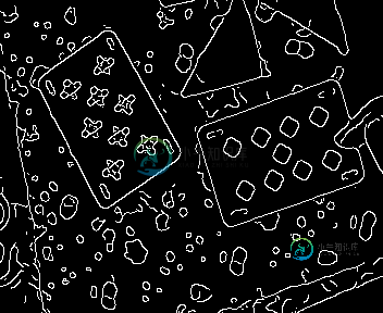
我想检查每个Canny检测到的边缘,并寻找其中的主线(以检查它们是否似乎形成矩形,例如,如果2对线是平行的等)。)。
Imgproc。HoughLinesP做了我想要的,但它给出了整个图像的线条,我想知道哪些线条来自相同的边缘。
我也尝试了FindContour,并用大约PolyDP在每个轮廓中寻找主线,但这看起来不合适,因为Canny检测到的边缘经常有缺口。这给出了边缘的轮廓,而不是边缘本身。
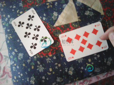
下面是一个测试图像示例:


如何为每个形状获得一组线条?
共有2个答案
如果您使用的是OpenCV 3.0.0,则可以使用LineSegmentDetector,以及“和”检测到的具有轮廓的线条。
我在下面提供了一个示例代码。这是C(很抱歉),但您可以轻松地用Java进行翻译。至少您了解了如何使用LineSegmentDetector以及如何为每个轮廓提取公共线。您将看到同一轮廓上具有相同颜色的线条。
#include <opencv2/opencv.hpp>
using namespace cv;
using namespace std;

int main()
{
    RNG rng(12345);
    Mat3b img = imread("path_to_image");
    Mat1b gray;
    cvtColor(img, gray, COLOR_BGR2GRAY);

    Mat3b result;
    cvtColor(gray, result, COLOR_GRAY2BGR);

    // Detect lines
    Ptr<LineSegmentDetector> detector = createLineSegmentDetector();
    vector<Vec4i> lines;
    detector->detect(gray, lines);

    // Draw lines
    Mat1b lineMask(gray.size(), uchar(0));
    for (int i = 0; i < lines.size(); ++i)
    {
        line(lineMask, Point(lines[i][0], lines[i][1]), Point(lines[i][2], lines[i][3]), Scalar(255), 2);
    }

    // Compute edges
    Mat1b edges;
    Canny(gray, edges, 200, 400);

    // Find contours
    vector<vector<Point>> contours;
    findContours(edges.clone(), contours, CV_RETR_EXTERNAL, CV_CHAIN_APPROX_NONE);

    for (int i = 0; i < contours.size(); ++i)
    {
        // Draw each contour
        Mat1b contourMask(gray.size(), uchar(0));
        drawContours(contourMask, contours, i, Scalar(255), 2); // Better use 1 here. 2 is just for visualization purposes

        // AND the contour and the lines
        Mat1b bor;
        bitwise_and(contourMask, lineMask, bor);

        // Draw the common pixels with a random color
        vector<Point> common;
        findNonZero(bor, common);

        Vec3b color = Vec3b(rng.uniform(0, 255), rng.uniform(0, 255), rng.uniform(0, 255));
        for (int j = 0; j < common.size(); ++j)
        {
            result(common[j]) = color;
        }
    }


    imshow("result", result);
    waitKey();

    return 0;
}
根据三木的回答,以下是我所做的:
- 坎尼
- HoughLinesP(或LineSegmentDetector,如您所想):检测行
- 连接组件:在Canny图像中找到Canny轮廓。
- 用3x3内核扩展(见下文)
- 对于每个Hough行:从行中取几个像素并寻找最频繁的值(忽略0)。例如,我选择了
{p1,0.75*p1 0.25*p2,0.5*p1 0.5*p2,0.25*p1 0.75*p2, p2},所以如果我的值是{1,2,0,2,2},那么该行属于ConnectedComponent数字2。扩展是为了确保你没有错过一个轮廓只有一个像素(但是如果你的对象太接近,不要使用它)。
这允许用轮廓线所属的颜色“标记”轮廓线。
所有这些函数都可以在Imgproc模块中找到,它仅在OpenCV 3.0中工作,并提供所需的结果。
下面是一个代码:
// open image
File root = Environment.getExternalStorageDirectory();
File file = new File(root, "image_test.png");

Mat mRGBA = Imgcodecs.imread(file.getAbsolutePath());
Imgproc.cvtColor(mRGBA, mRGBA,  Imgproc.COLOR_BGR2RGB);

Mat mGray = new Mat();
Imgproc.cvtColor(mRGBA, mGray, Imgproc.COLOR_RGBA2GRAY);

Imgproc.medianBlur(mGray, mGray, 7);

/* Main part */

Imgproc.Canny(mGray, mGray, 50, 60, 3, true);

Mat aretes = new Mat();
Imgproc.HoughLinesP(mGray, aretes, 1, 0.01745329251, 30, 10, 4);

/**
 * Tag Canny edges in the gray picture with indexes from 1 to 65535 (0 = background)
 * (Make sure there are less than 255 components or convert mGray to 16U before)
 */
int nb = Imgproc.connectedComponents(mGray,mGray,8,CvType.CV_16U);

Imgproc.dilate(mGray, mGray, Imgproc.getStructuringElement(Imgproc.MORPH_RECT, new Size(3,3)));


// for each Hough line
for (int x = 0; x < aretes.rows(); x++) {
     double[] vec = aretes.get(x, 0);
     double x1 = vec[0],
            y1 = vec[1],
            x2 = vec[2],
            y2 = vec[3];

     /**
      * Take 5 points from the line
      *
      *   x----x----x----x----x
      *   P1                  P2
      */
        double[] pixel_values = new double[5];
        pixel_values[0] = mGray.get((int) y1, (int) x1)[0];
        pixel_values[1] = mGray.get((int) (y1*0.75 + y2*0.25), (int) (x1*0.75 + x2*0.25))[0];
        pixel_values[2] = mGray.get((int) ((y1 + y2) *0.5), (int) ((x1 + x2) *0.5))[0];
        pixel_values[3] = mGray.get((int) (y1*0.25 + y2*0.75), (int) (x1*0.25 + x2*0.75))[0];
        pixel_values[4] = mGray.get((int) y2, (int) x2)[0];

        /**
         * Look for the most frequent value
         * (To make it readable, the following code accepts the line only if there are at
         * least 3 good pixels)
         */
        double value;
        Arrays.sort(pixel_values);

        if (pixel_values[1] == pixel_values[3] || pixel_values[0] == pixel_values[2] || pixel_values[2] == pixel_values[4]) {
            value = pixel_values[2];
        }
        else {
            value = 0;
        }

        /**
         * Now value is the index of the connected component (or 0 if it's a bad line)
         * You can store it in an other array, here I'll just draw the line with the value
         */
        if (value != 0) {
            Imgproc.line(mRGBA,new Point(x1,y1),new Point(x2,y2),new Scalar((value * 41 + 50) % 255, (value * 69 + 100) % 255, (value * 91 + 60) % 255),3);
        }
}

Imgproc.cvtColor(mRGBA, mRGBA, Imgproc.COLOR_RGB2BGR);
File file2 = new File(root, "image_test_OUT.png");
Imgcodecs.imwrite(file2.getAbsolutePath(), mRGBA);
-
问题内容: 我想从均匀分布的2D数据(类似图像的数据)的单个轮廓中获取数据。 基于在类似问题中找到的示例:如何获得轮廓图(matplotlib)绘制的线的(x,y)值? 该调用的结果是: 基于这些图,此结果是有意义的,并且似乎是轮廓线的(y,x)对的集合。 除了手动遍历此返回值,提取直线的坐标并组装线的数组以外,还有更好的方法从对象取回数据吗?从中提取数据时是否有陷阱要注意? 或者,是否有其他选择
-
我想提取图像的轮廓,用点坐标序列表示。 使用,我能够生成一个只包含图像边缘的二进制图像。然后,我尝试使用来提取轮廓。不过,结果并不好。 对于每一条边,我通常得到两条线,就像它被认为是一个非常薄的区域一样。我想简化我的轮廓,这样我可以把它们画成单线。或者用不同的函数提取它们,直接产生正确的结果会更好。 我查看了OpenCV的文档,但没有找到任何有用的东西,但我想我不是第一个遇到类似问题的人。有什么功
-
我有3个maven项目A、B、C。A是B的父项目,B是C的父项目。所有概要文件都在pom中定义。项目A的xml。 在项目C中,我试图根据所选概要文件在spring测试上下文中选择属性文件(在src/test/resources下)。对于回归测试,我们有两个属性文件: 本地应用程序测试。属性 在我们的Windows开发系统上,选定的配置文件将是“本地”的,相应地在服务器上也是如此。选择“本地”配置文
-
问题内容: 我正在尝试从Material-UI模仿概述的文本字段,但是我不知道如何在标题文本后面隐藏边框。 在下图中,请注意如何从Material-UI库中获取“到期日期/时间”,标题隐藏了边框,但当我尝试使用自定义组件模仿它时,我只是无法隐藏边框。 另外,是否有更好的方法来使用此轮廓设计,而不是仅使用CSS来实现? 我当前的组件看起来像这样: 问题答案: 更新 在许多情况下,我的后续答案(避免使
-
主要内容:1. outline-style,2. outline-width,3. outline-color,4. outline,5. outline-offset轮廓(outline)是绘制于元素周围的一条线,位于边框的外围(紧贴着边框),主要用来突出显示某个元素,如下图所示: 图:轮廓(outline) 轮廓和边框看起来非常相似,但它们之间也并非没有区别,例如: 元素上下左右四个方向上边框的样式、宽度、颜色可以单独设置,而轮廓在元素四个方向的宽度、样式、颜色都是相同的,不能单独设置; 边
-
我有2个URL,其中1个特定于Dev,另一个特定于Prod。我也在使用Spring profiling,其中我有一个单独的文件用于Dev和Prod application-Dev。性能和应用-prod。属性和我的应用。对于Dev env,属性文件如下所示 spring.profiles.active=dev 现在在我的java代码中,我想有一个属性,它将根据我使用的Spring配置文件绑定到适当的

