Arduino - 连接开关( Connecting Switch)
优质
小牛编辑
140浏览
2023-12-01
按钮或开关连接电路中的两个开路端子。 当您按下连接到引脚8的按钮开关时,此示例将打开引脚2上的LED。

Pull-down Resistor
下拉电阻用于电子逻辑电路,以确保如果外部器件断开或处于高阻态,Arduino的输入将达到预期的逻辑电平。 由于没有任何东西连接到输入引脚,因此并不意味着它是逻辑零。 下拉电阻连接在地和设备上的相应引脚之间。
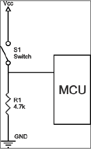
数字电路中的下拉电阻示例如下图所示。 按钮开关连接在电源电压和微控制器引脚之间。 在这样的电路中,当开关闭合时,微控制器输入处于逻辑高值,但是当开关打开时,下拉电阻将输入电压拉低至地(逻辑零值),从而防止输入处的未定义状态。
下拉电阻必须具有比逻辑电路的阻抗更大的电阻,否则它可能将电压拉得太低并且引脚的输入电压将保持在恒定的逻辑低值,而不管开关位置如何。

组件的要求 (Components Required)
您将需要以下组件 -
- 1×Arduino UNO板
- 1×330欧姆电阻器
- 1×4.7K欧姆电阻(下拉)
- 1×LED
过程 (Procedure)
按照电路图进行连接,如下图所示。

草图 (Sketch)
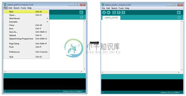
在您的计算机上打开Arduino IDE软件。 用Arduino语言编码将控制你的电路。 单击“新建”打开新的草图文件。

Arduino代码 (Arduino Code)
// constants won't change. They're used here to
// set pin numbers:
const int buttonPin = 8; // the number of the pushbutton pin
const int ledPin = 2; // the number of the LED pin
// variables will change:
int buttonState = 0; // variable for reading the pushbutton status
void setup() {
   // initialize the LED pin as an output:
   pinMode(ledPin, OUTPUT);
   // initialize the pushbutton pin as an input:
   pinMode(buttonPin, INPUT);
}
void loop() {
   // read the state of the pushbutton value:
   buttonState = digitalRead(buttonPin);
   // check if the pushbutton is pressed.
   // if it is, the buttonState is HIGH:
   if (buttonState == HIGH) {
      // turn LED on:
      digitalWrite(ledPin, HIGH);
   } else {
      // turn LED off:
      digitalWrite(ledPin, LOW);
   }
}
Code to Note
当开关打开时,(按钮没有按下按钮),按钮的两个端子之间没有连接,所以引脚连接到地(通过下拉电阻),我们读低电平。 当开关闭合(按下按钮)时,它在两个端子之间建立连接,将引脚连接到5伏,这样我们就读取了一个HIGH。
结果 (Result)
按下按钮时LED指示灯亮,释放按钮时指示灯熄灭。

